It became apparent at the end of September that the first order of business for building the interior was to install the cabin sides. Once the cabin sides are in the overhead cleats which support the plywood "V-groove" paneling and the false beams can be installed (I'll use 5200 to secure them to the overhead). To get the spacing right I needed to get the cabin sides in first. Also, because I will use 5200 to secure the 1/2" mahogany ply to the cabin top sides, I need to install them before I install the interior, else the 5200 drip down on the vertical staving and . . . well it would be a mess. It takes a lot of planning to get the sequence correct for the many individual projects I don't inadvertently install something that makes the next task more difficult. Since this is my first time building a boat interior I have a very limited knowledge base to rely on. I have to slow down, think about it, research it, draw it out.
I had planned on using the "mish-mash" trim rings that were part of the original interior. You can see them in the first photo below. They were installed to fill the gap between the one piece fiberglass headliner and the FRP cabin trunk. I wanted to incorporate them because they were molded to the bronze Spartan port-lights. But, to use them would have created an air gap between the backside of the plywood sides and the FRP cabin trunk. Additionally, the depth of the port-light spigots could not properly span the thickness of the ply, the "mish-mash" trim rings, FRP cabin side, and external bronze port-light trim ring. So what to do? I drew out some schematics, revised, measured some more, revised again, considered, talked to boat builders I trusted, and then thoughts some more. Finally, I decided to removed the mish-mash trim rings. They came off in an hour with a chisel and mallet. Then I sanded the inside of the cabin side smooth and while I was at it, because I love grinding and sanding fiberglass so much, I sanded the over head some more where the cleats will go that will support the false beams.
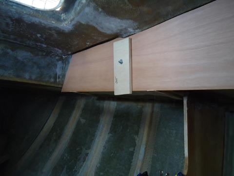
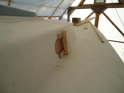
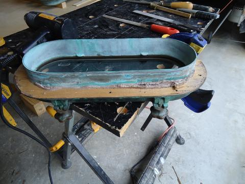
Next, I bought a couple of sheets of 1/2" type I marine grade mahogany plywood. I thought about how far down the trim would need to go on the bottom edge of the plywood cabin sides. I would like to incorporate a drip rail and I would like to have some false beams under the side deck to cover the seams in the 1/4" ply "v-groove" panels, etc, so the trim would have to accommodate these things. I made some more diagrams. To support the buildings of the patterns on the cabin side and to make sure the bottom edge would be lined up properly I fastened some temporary cleats to the underside of the side deck with a hot glue gun. Then, I made patterns with doorskin strips and hot glue gun. I secured the patterns on the cleat ledges and clamped them to the cabin side through the portholes with squeeze clamps. I took the patterns down and laid them on the 1/2" mahogany ply. Normally, I like to lay them on the back side of the ply I am working on and cut them face down so the edge is cleaner from saws that cut upward. But, I wanted to match up the wood grain pattern I best as I could so I marked and cut them face up. I took the freshly cut ply up to the boat. To hold them in place I had made up some clamps that would hold the plywood sides tight to the FRP cabin side after I applied the 5200. What I came up with were plywood backing plates, some bolts, and 2x4 braces. I drilled a hole through the backing plate, then with my wife holding the plywood in place, drilled through the plywood in the areas that would eventually be cut out to make room for the port-lights, then through the 2x4 brace. A bolt was inserted through all these holes and tightened forcing the ply against the FRP cabin side. It seemed to work well. Once I had all the ply temporarily clamped on the starboard side, I looked it over. I was satisfied with the plan.
I removed the plywood and took them into the wood shop. I laid some plastic over the assembly table in the garage. I taped the edges of the mahogany side of the ply to protect them from any drips and flipped the ply over and laid it across some 1"x1" sticks with the plastic mahogany side down. Then, I mixed up some unthickend epoxy and rolled it on to seal the back side of the ply. I dragged a foam roller, cut length wise in thirds with a strip of wood for a handle, to removed any bubbles. I finished off by carefully brushing epoxy along all the edges of the ply to seal it as much as possible. No matter how much you work to maintain your boat, water will eventually find its way into any holes. Hopefully, the sealed wood will provide some protection if I wait to long to rebed the port-lights. After the epoxy was tacky to the touch I applied a second coat.
In between the work on the plywood cabin sides today I applied two more layers of 17.7oz epoxy tape to two bulkheads. They did not have a proper radiused corner against the skin of the FRP cabin side. It was a mistake I made last year but now was the time to correct it.
Tomorrow I go look at some quarter sawn black walnut to see if it will be suitable for a cabin sole.
I had planned on using the "mish-mash" trim rings that were part of the original interior. You can see them in the first photo below. They were installed to fill the gap between the one piece fiberglass headliner and the FRP cabin trunk. I wanted to incorporate them because they were molded to the bronze Spartan port-lights. But, to use them would have created an air gap between the backside of the plywood sides and the FRP cabin trunk. Additionally, the depth of the port-light spigots could not properly span the thickness of the ply, the "mish-mash" trim rings, FRP cabin side, and external bronze port-light trim ring. So what to do? I drew out some schematics, revised, measured some more, revised again, considered, talked to boat builders I trusted, and then thoughts some more. Finally, I decided to removed the mish-mash trim rings. They came off in an hour with a chisel and mallet. Then I sanded the inside of the cabin side smooth and while I was at it, because I love grinding and sanding fiberglass so much, I sanded the over head some more where the cleats will go that will support the false beams.
Next, I bought a couple of sheets of 1/2" type I marine grade mahogany plywood. I thought about how far down the trim would need to go on the bottom edge of the plywood cabin sides. I would like to incorporate a drip rail and I would like to have some false beams under the side deck to cover the seams in the 1/4" ply "v-groove" panels, etc, so the trim would have to accommodate these things. I made some more diagrams. To support the buildings of the patterns on the cabin side and to make sure the bottom edge would be lined up properly I fastened some temporary cleats to the underside of the side deck with a hot glue gun. Then, I made patterns with doorskin strips and hot glue gun. I secured the patterns on the cleat ledges and clamped them to the cabin side through the portholes with squeeze clamps. I took the patterns down and laid them on the 1/2" mahogany ply. Normally, I like to lay them on the back side of the ply I am working on and cut them face down so the edge is cleaner from saws that cut upward. But, I wanted to match up the wood grain pattern I best as I could so I marked and cut them face up. I took the freshly cut ply up to the boat. To hold them in place I had made up some clamps that would hold the plywood sides tight to the FRP cabin side after I applied the 5200. What I came up with were plywood backing plates, some bolts, and 2x4 braces. I drilled a hole through the backing plate, then with my wife holding the plywood in place, drilled through the plywood in the areas that would eventually be cut out to make room for the port-lights, then through the 2x4 brace. A bolt was inserted through all these holes and tightened forcing the ply against the FRP cabin side. It seemed to work well. Once I had all the ply temporarily clamped on the starboard side, I looked it over. I was satisfied with the plan.
I removed the plywood and took them into the wood shop. I laid some plastic over the assembly table in the garage. I taped the edges of the mahogany side of the ply to protect them from any drips and flipped the ply over and laid it across some 1"x1" sticks with the plastic mahogany side down. Then, I mixed up some unthickend epoxy and rolled it on to seal the back side of the ply. I dragged a foam roller, cut length wise in thirds with a strip of wood for a handle, to removed any bubbles. I finished off by carefully brushing epoxy along all the edges of the ply to seal it as much as possible. No matter how much you work to maintain your boat, water will eventually find its way into any holes. Hopefully, the sealed wood will provide some protection if I wait to long to rebed the port-lights. After the epoxy was tacky to the touch I applied a second coat.
In between the work on the plywood cabin sides today I applied two more layers of 17.7oz epoxy tape to two bulkheads. They did not have a proper radiused corner against the skin of the FRP cabin side. It was a mistake I made last year but now was the time to correct it.
Tomorrow I go look at some quarter sawn black walnut to see if it will be suitable for a cabin sole.
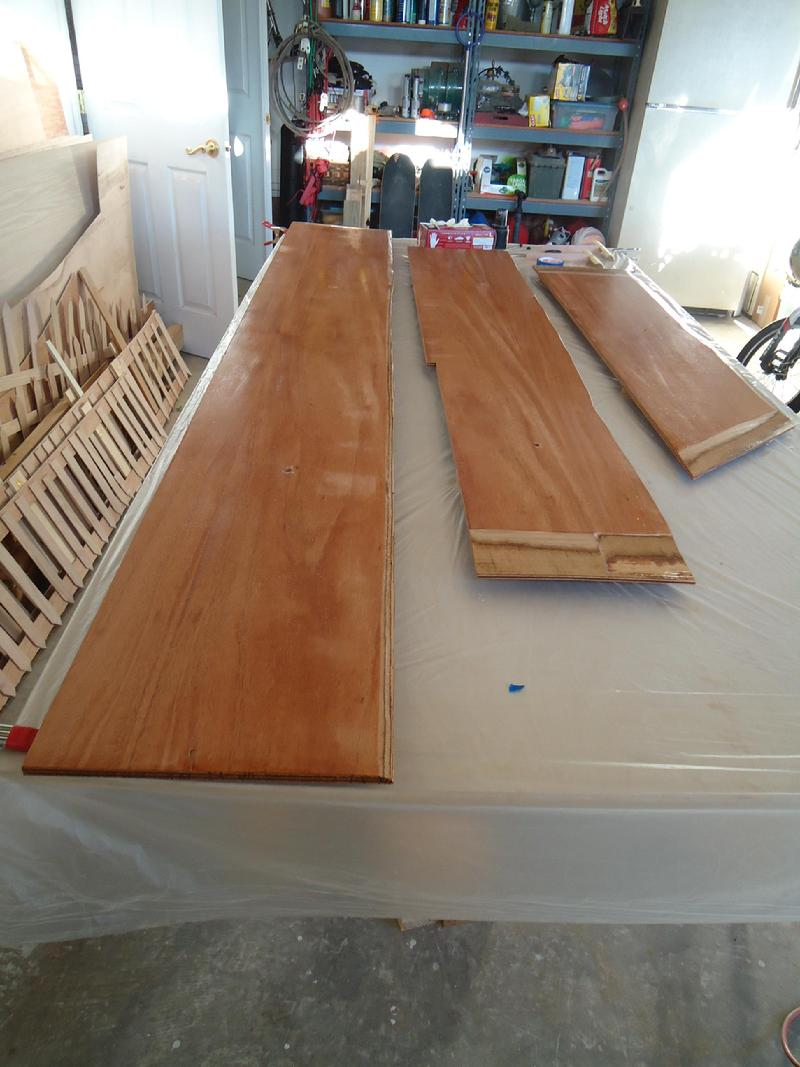
Two layers of epxoy to seal the back side of the plywood.
Below:
1. The original "mish-mash" trim rings.
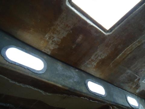
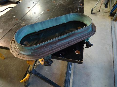
2. After the trim rings were removed.
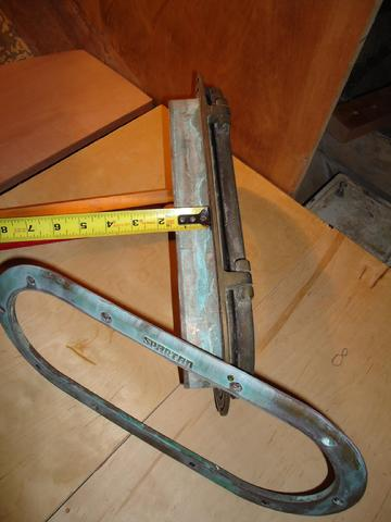
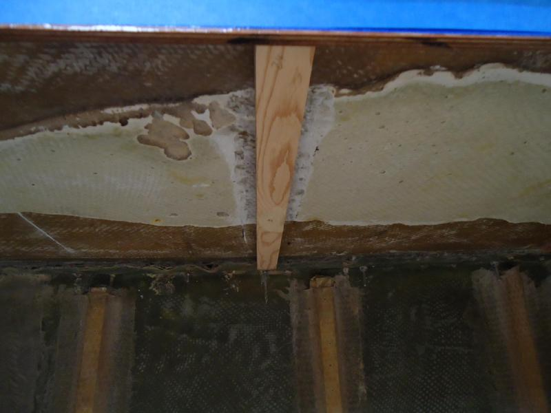
3. 1 3/8" spigot depth.
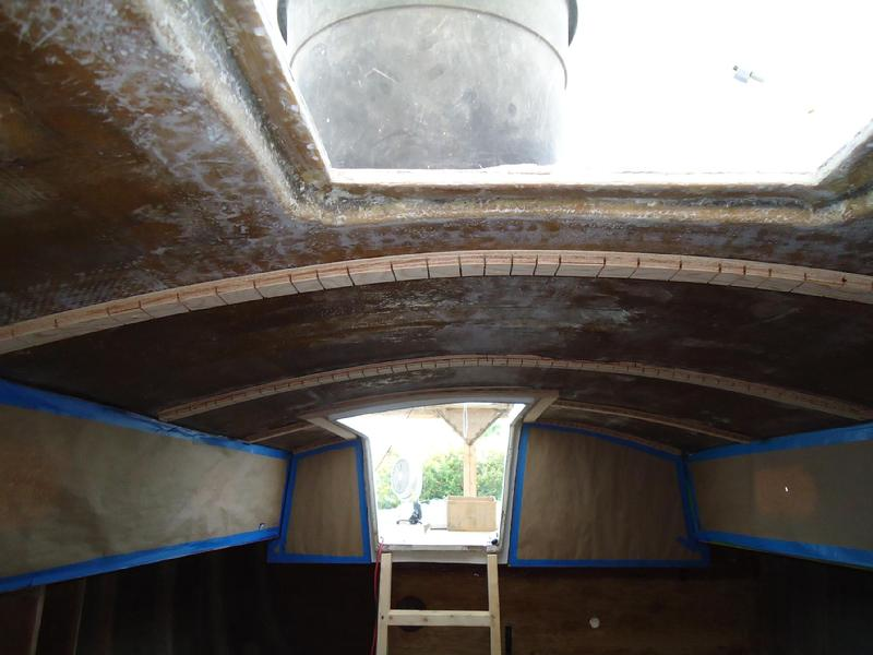
4. The sanding complete for the overhead cleats.
5. The sanding complete for the overhead cleats.
6.
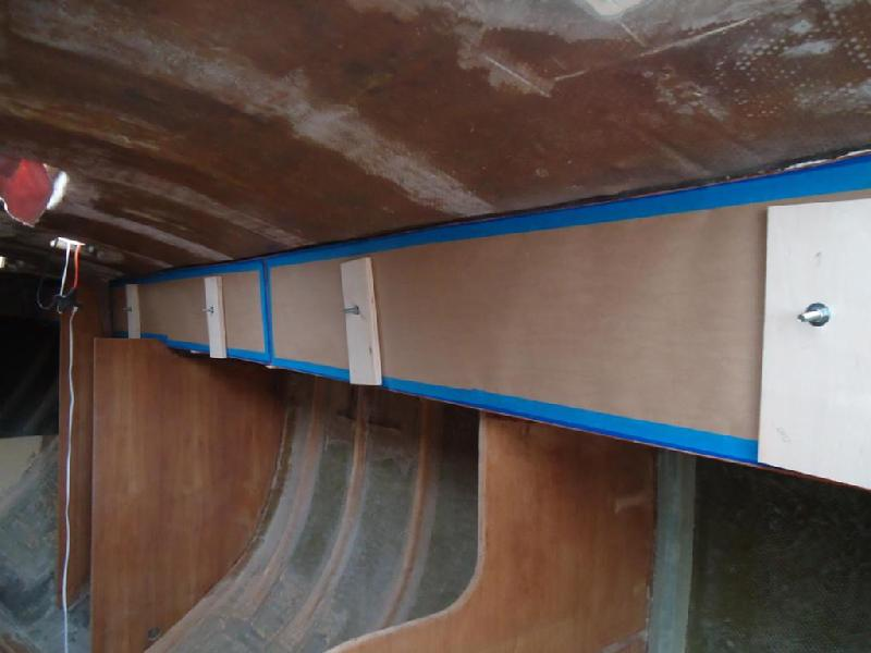
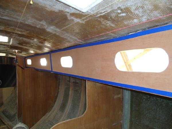
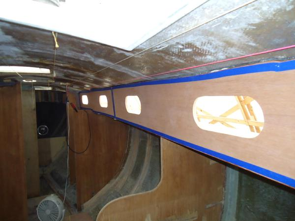
7. Mahogany ply cabin side in the forward cabin.
8. The external backing brace for the clamp system.
Yesterday, I drove to Winston-Salem NC to meet with Ken Elliot who has his own saw mill. A very interesting guy with a pretty neat setup. All though I was there only a short time I learned a lot. He had some beautiful walnut. We discussed both quartersawn and plain sawn and the advantages and disadvantages of both. I have about 50 sq feet of sole to cover. This will, of course, require that I buy more than 50 boad feet since I will buy it 5/4 rough milled and there will be some wastage. My task now is to decide between QS and PS.
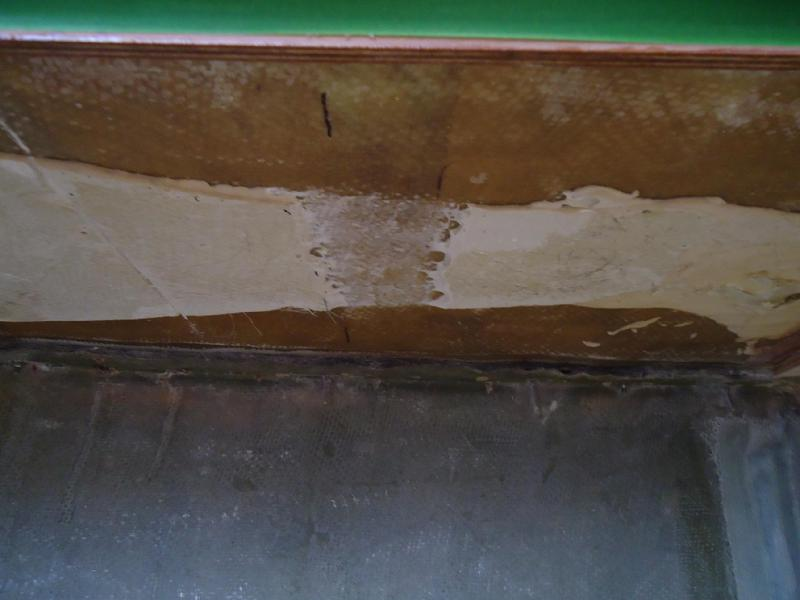
I spent the day with my family but this afternoon I managed to mix up some fairing compound and spread it around the portholes and then faired it with a straight edge and a plastic squeegee. The FRP cabin side are not perfectly flush with the plywood when it is placed against it. This results in a few gaps around the edges of the portholes between the FRP and ply. Hopefully this will result in a better fit.
I spent the day with my family but this afternoon I managed to mix up some fairing compound and spread it around the portholes and then faired it with a straight edge and a plastic squeegee. The FRP cabin side are not perfectly flush with the plywood when it is placed against it. This results in a few gaps around the edges of the portholes between the FRP and ply. Hopefully this will result in a better fit.
Prepping the cabin sides with fairing compound.
Today I sanded the fairing compound I applied around the portholes yesterday. Then I temporarily installed the full starboard side mahogany plywood paneling. The tape was applied to protect the mahogany veneer while I rolled and brushed two coats of epoxy to the back and edges of the plywood the day before yesterday. Before I permanently install the ply with 5200 I will protect the veneer with thick brown paper and tape. I don't want to varnish yet, thought that would be a good way to protect the veneer from 5200 seepage. I will screw and glue the lower trim and I don't know where the edge of the trim will be located so I don't really want to varnish yet. Also, the best place to varnish, at the moment, is on the boat. There is just too much dust and traffic in the wood shop or garage.
After putting up the panels on the starboard side I built the patterns for the portside. Tomorrow I will cut out the port side panels and apply epoxy coating the back and edges of the ply. I'll make up some more bracing and backing plates. I'll also tape and apply protective plastic sheeting around the outside of the portholes to limit the mess created by 5200 squeeze out.
After putting up the panels on the starboard side I built the patterns for the portside. Tomorrow I will cut out the port side panels and apply epoxy coating the back and edges of the ply. I'll make up some more bracing and backing plates. I'll also tape and apply protective plastic sheeting around the outside of the portholes to limit the mess created by 5200 squeeze out.
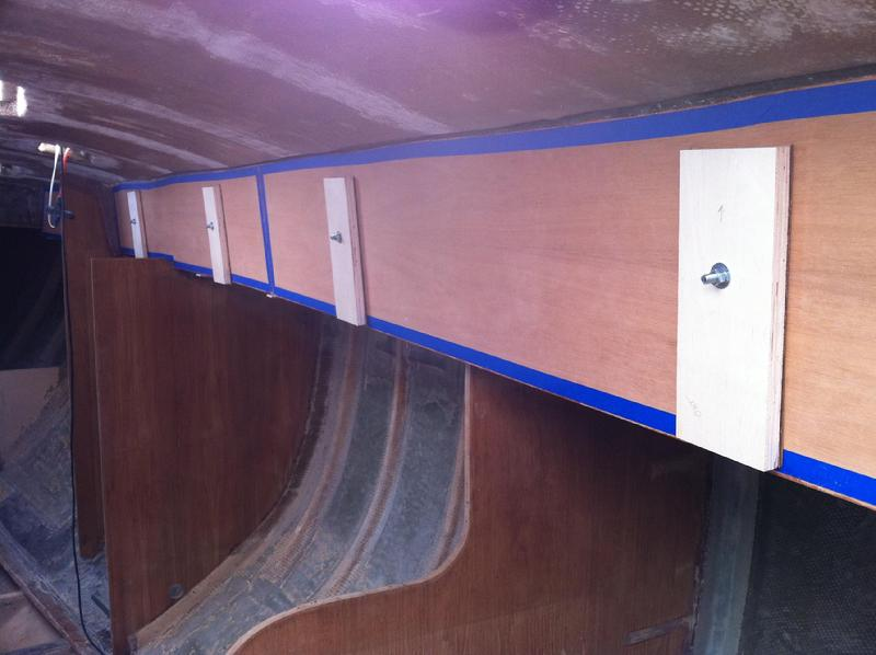
Temporary fitting of the starboard cabin side.
Smooth sailing today . . . so to speak. My friend Ron Mason came by to lend me a hand with clamping the mahogany plywood to the port and starboard cabin sides. Yesterday, I took the patterns I had made for the port cabin side the day before and traced them onto 1/2" marine grade mahogany plywood. I followed the same procedure that I used on the starboard side. After I beveled the edges to get a better fit along the curved edges of the cabin top I applied two coats of unthickend West Systems epoxy. I also made more bracket-clamps so I could clamp the ply to both cabin sides at the same time. I decided to save the limited number of tubes of quick-set 5200 that I have for another project and use regular 5200 instead.
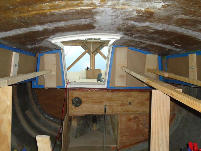
We taped off the fiberglass around the portholes on the outside with painters tape and brown paper to reduce the mess caused by any squeeze out. We also covered the good side of the african mahogany with brown paper (which you can see in the photos) to protect them from any 5200 we might inadvertently get on our hands. Next, with the ply temporarily clamped in place, we used an indelible marker to traced the porthole edges on the backside of the ply. Then we applied 5200 directly to the plywood. We laid beads around the portholes, along the edges of the ply and back and fourth across the panel. Then, with Ron on the outside pushing the bolts through, I held the panels in place until we could fit the cardboard protectors, backing plates, washer in place and screw on the nuts. Then we tightened the nuts down with a socket wrench until we got good squeeze-out around the portholes. It went very smooth. No problems, no drips, and no mess. Easy day. They need to stay clamped for seven days.
Tomorrow I will start making the templates for the plywood to cover the forward face of the cabin and the two athwartship section on each side of the companionway ladder.
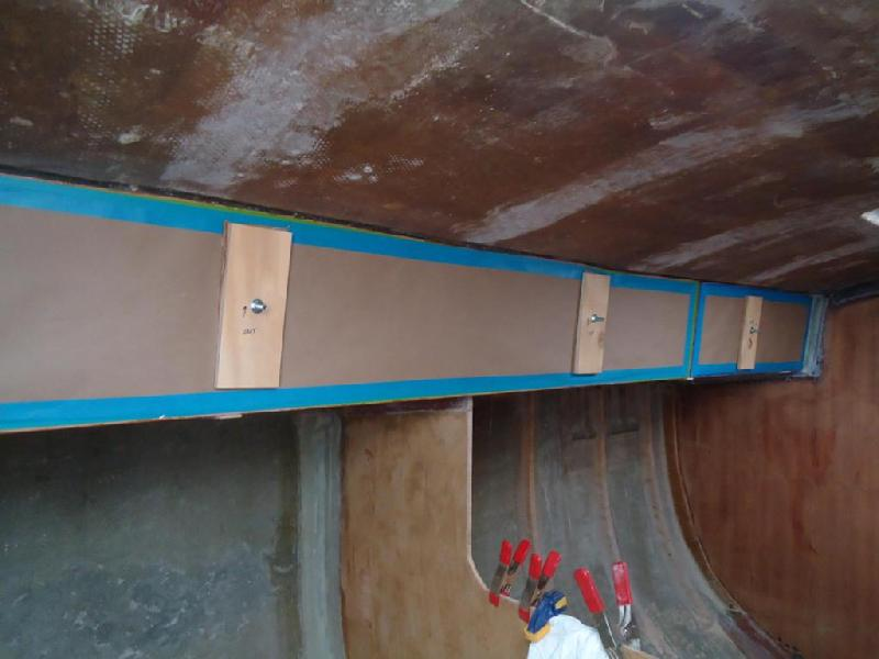
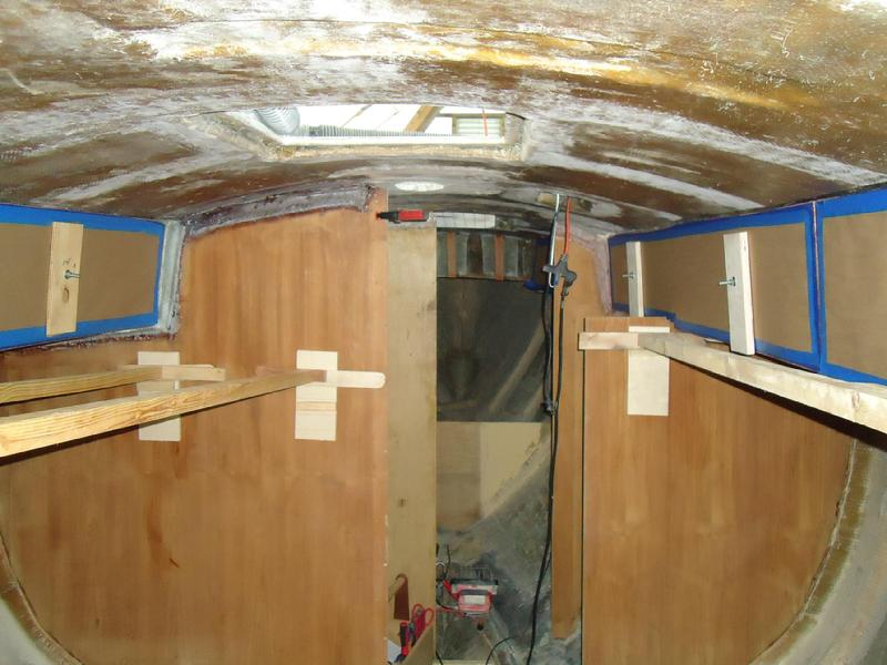
Port side mahogany ply "glued" with 5200 and clamped in place.
Staboard side clamped in place.
This was supposed to be an easy day. All I had to do was to install the last two panels on the aft side of the cabin house and use quick set 5200 so they would only need to be braced for 24 hours. How hard could it be? I had no difficulties putting up the side panels earlier in the week and that was a much more complicated project. The only challenge for this simple project was that I would have to use some long (about 12 feet) "dead-men" to apply pressure to the panels. The braces would be wedged between the panels to be installed and the main saloon bulkheads. I would need to clamp some ply wood supports on the intermediate bulkheads to support the middle of the dead-men. I used backing plates (3/4" ply" to protect the wood though the saloon bulkheads will eventually be covered with 3/8" thick vertical "v-groove" African Mahogany staving) and double wedges that I would drive in to apply more compression to the panels. Before I installed them, I prepared the panels by washing off the amine blush on the back side that I had coated with two coats of epoxy the day before. Then I roughed them up with 80 grit paper on a RO sander. I vacuumed and then wiped them down with acetone. Because the dead-men were so long I needed some extra hands so my wife helped. We rehearsed each step with a dry run. Everything went fine. With the front side of the panels covered in brown paper to protect the mahogany I applied quick set 5200 to the back side. We got the panels up and the dead-men in place. I hammered in the double set of wedges to apply compression. Done! "Nice job John . . . you're a pretty smart fellow to come up with this plan." Then as I was leaving for the day I noticed one of the panels was slipping down! I pushed up on it and I could just move it back into place. I ended up having to quickly cut some supports for the bottom edge of the panel while my wife held the panel in place. I laid down a temporary floor beam from the step that supports the bottom of the companionway ladder horizontal to the hull. I added some padding and then cut a 2"x2" support that fit between the temporary beam to the bottom edge of the panel. Then quickly removed the wedges and reset the angle for the dead-men so there was more upward pressure. This was quick set 5200 and it sets up pretty quick. So it was rush, rush, rush, hurry, cut, and drive the wedges in again. I guess I was just lucky to have looked at the panel one more time before I left for the day. Sometimes luck is more important than skill. It turns out this was all caused by the fact that the back of the cabin top slopes down and a little aft. I originally had the dead-men set horizontally applying pressure straight back. So, the panels went the only place they could to escape the pressure . . . down. I noted that the cabin sloped back the other day but dismissed it as unimportant. Ha! That will teach me to ignore simply physics and the laws of gravity.
Bracing the paper protected mahogany plywood in place.xt
Double wedges driven in to increase compression.xt
Yesterday I removed the deadmen that were serving as braces for the plywood panels adjacent to the companionway ladder. It worked out very nicely and I am pleased with the results. I spent the rest of the day mapping out the overhead for cleating. This is important because the inside skin of the overhead is not smooth and even like the outside. I have to address these dips and bumps before I cleat the inside skin or the final product (v-groove panels and mahogany beams) will not be straight.
Today, I removed the clamps that had been holding the mahogany ply wood panels on the cabin top sides for the last seven days. Next, I removed the paper carefully so I could reuse it after I cut out the portholes. The plywood needs to be protected until I can apply several coats of varnish which I plan to do after the portholes are cut out and the overhead cleats are installed.
In order to cut consistent holes of the proper size I made a jig by tracing around the spigot of one of the bronze Spartan portlights on a piece of plywood. I used a jig saw to cut the hole out slightly larger than the spigot. I carefully sanded it smooth. Though counterintuitive, a portlight spigot that fits too tightly has an increased risk of leaking because you can't get the proper amount of sealant between the spigot and the surrounding wood/fiberglass.
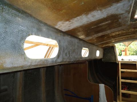
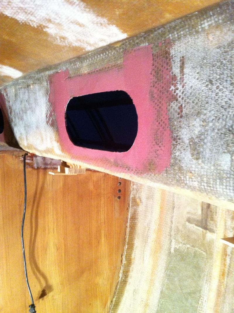
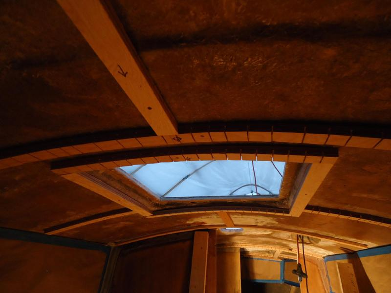
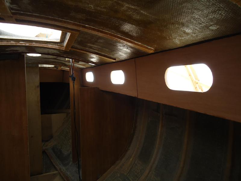
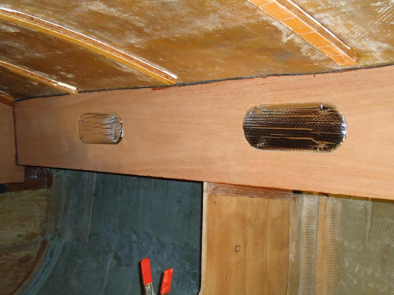
Next, I placed the jig over the old porthole cut out, still visible from outside the cabin and traced the slightly smaller hole on the plywood. I used a level to make sure the tops were horizontal. However, the forward two holes are angled up slightly. That is the way they were cut from the factory and there isn't room to level them. The cabin top is level/horizontal but as the shear of the boat/deck rises the relative height of the cabin side is reduced, thus less room for the portlight. You can see this different angle from the photo taken inside the boat. Note the aft most three are level and then the next/fourth porthole is angled up. After I I traced the new holes I used a jigsaw to cut the holes out.
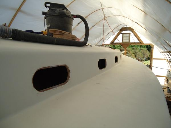
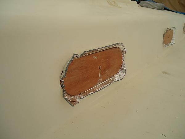
What a difference in how the boat looks from outside and inside. The FRP cabin side has a slightly bigger hole (original hole--and cut pretty poorly I might add) than the hole in the plywood I cut today. You can see it in the photo shot from the outside of the boat. The slightly smaller hole in the plywood will allow me to take the jig I made today and clamp it in place tomorrow whereupon I will use the inside edge as a template to cut the proper size hole with a router and laminate bit. The bearing on the laminate bit will ride against the plywood template to ensure a smooth clean cut. Once that is complete I will slightly champher the edge of the plywood hole from the inside and then lay on several coats of epoxy to seal the exposed edge of the plywood. By having a slightly larger chamfered hole I can better fill the gap with butyl rubber and seal it properly. That way, the portlight will be "floating" in the hole and can expand and shrink as it is heated and cooled from changing outside temperatures. The gap needs to be large enough to fill it with enough butyl rubber to provide the elongation necessary to resist breaking the seal. Right now, I don't plan to install the portholes till next spring, after I paint the outside of the boat.
Today, I removed the clamps that had been holding the mahogany ply wood panels on the cabin top sides for the last seven days. Next, I removed the paper carefully so I could reuse it after I cut out the portholes. The plywood needs to be protected until I can apply several coats of varnish which I plan to do after the portholes are cut out and the overhead cleats are installed.
In order to cut consistent holes of the proper size I made a jig by tracing around the spigot of one of the bronze Spartan portlights on a piece of plywood. I used a jig saw to cut the hole out slightly larger than the spigot. I carefully sanded it smooth. Though counterintuitive, a portlight spigot that fits too tightly has an increased risk of leaking because you can't get the proper amount of sealant between the spigot and the surrounding wood/fiberglass.
Next, I placed the jig over the old porthole cut out, still visible from outside the cabin and traced the slightly smaller hole on the plywood. I used a level to make sure the tops were horizontal. However, the forward two holes are angled up slightly. That is the way they were cut from the factory and there isn't room to level them. The cabin top is level/horizontal but as the shear of the boat/deck rises the relative height of the cabin side is reduced, thus less room for the portlight. You can see this different angle from the photo taken inside the boat. Note the aft most three are level and then the next/fourth porthole is angled up. After I I traced the new holes I used a jigsaw to cut the holes out.
What a difference in how the boat looks from outside and inside. The FRP cabin side has a slightly bigger hole (original hole--and cut pretty poorly I might add) than the hole in the plywood I cut today. You can see it in the photo shot from the outside of the boat. The slightly smaller hole in the plywood will allow me to take the jig I made today and clamp it in place tomorrow whereupon I will use the inside edge as a template to cut the proper size hole with a router and laminate bit. The bearing on the laminate bit will ride against the plywood template to ensure a smooth clean cut. Once that is complete I will slightly champher the edge of the plywood hole from the inside and then lay on several coats of epoxy to seal the exposed edge of the plywood. By having a slightly larger chamfered hole I can better fill the gap with butyl rubber and seal it properly. That way, the portlight will be "floating" in the hole and can expand and shrink as it is heated and cooled from changing outside temperatures. The gap needs to be large enough to fill it with enough butyl rubber to provide the elongation necessary to resist breaking the seal. Right now, I don't plan to install the portholes till next spring, after I paint the outside of the boat.

I started off this morning working on the portlights. They have been out of the boat for about 14 months and have been in the SRF collecting dust. I washed them off in soapy water and laid them out to dry. While they were drying I went back to the boat and prepared to router out the holes I cut the day before with a saber saw. The base on a full size router is too big to get between the cabin top, the porthole opening, and the clamps I need to hold the template in place. I don't have a laminate router, which is smaller than a full size plunge router, but I do have a roto-zip with a wide base. With a 1/4" collet Bosch straight cut carbide bit and integral bearing I thought I could achieve the same results without having to buy another tool (I know, I can't believe I passed up the opportunity to acquire another tool when I actually had a good reason to get one). After wiping it down with acetone to remove any oil or grease, I covered the metal base of the roto-zip with plastic packing tape to protect the mahogany plywood. Then, I took the template I made a few days ago and made the opening a little bigger. I wanted the opening of the template to allow about 1/4" gap all the way around the portlight spigot.
By then my friend Ron Mason had come by to give me a hand and speed things along. We positioned the template over a porthole centering it more-or-less over the original holes (with the exception of the most forward porthole we were able to get them all level on top). Once we were satisfied with the position of the template we clamped it to the cabin side with three squeeze clamps. Then, with a mask, hearing protecting, tyvek sleeves, and gauntlet gloves I routered each hole flush with the template. Ron worked the vacuum from the outside, moved the clamps in succession always keeping at least two in place to prevent any movement of the template while repositioning the third clamp, and made sure the template was not moving. It went pretty fast and I am pleased with the results. The portholes have a much more refined look. It's always great to have a knowledgeable helping hand, especially someone as skilled with tools as Ron.
With the routering complete, Ron departed and I went back to cleaning up the portlights. With a heat gun, multi-tool scraper, SS brush, and a file I went to work. The original Sikaflex was pretty hard and firmly attached to the bronze flange. There was also a fair amount of silicone on the flange where the PO had attempted to stop leaks around the portholes--it didn't work as evidenced by the water streaks I discovered on the inside of the cabin top and hull of the boat when I gutted the Far Reach. Despite the thick hard Sikaflex, the heat gun worked wonders softening up the the old bedding compound and the multi tool worked well scraping it off. I was able to get five cleaned up before supper.
It feels pretty good to be moving along with some visible results inside the boat.
To see how the portlights were prepared and installed click here.
Installing Overhead Cleats
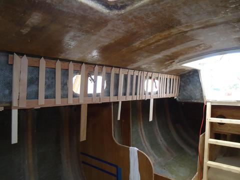
For the last several days I have been developing the plan for installing the overhead cleats that will support the anchoring of both the overhead v-groove panels and the deck beams. This required a lot of mapping with 3/4" blocks, hot glued in place, and string to better understand the surface of the underside of the deck. I also spent a lot of time just sitting in the boat looking at the overhead and sorting out how this project should unfold. Once I had a feel for what I was dealing with I began to install some cleats.
There are a lot of recesses and protrusions on the surface of the overhead. The outside edge where the overhead and the cabin top sides meet is very uneven. To achieve any sort of consistent camber I have to cut the ends of the cleats about an inch or so from the cabin top side. Some of the unevenness is caused by thick wood substituted for balsa core in the deck to reinforce high load areas. Others are due to extra roving and matting. Since the boat originally had a one piece fiberglass headliner the builders didn't have a reason to make sure the unseen skin was smooth and fair. To deal with these imperfections I cut shims for the low spots under the cleats and trimmed away some of the cleat in the high spots in order to get a smooth uniform camber. I initially tried to spring the 3/4" ply cleats in place without cutting kerfs but they snapped. So, almost all of the cleats running athwartship require kerfs. After they are attached with 5200 the kerfs will be filled with thickened epoxy.
To this point, I have only temporarily attached the cleats with some small self-tapping screws. Once I am satisfied that this is the right approach I'll attach them with 5200.
This is frustratingly slow work but when complete progress should pick up. The Refleks heater arrived a few days ago so I will have what I need to get the right measurements for the starboard settee modifications.
Test fitting the overhead cleats.
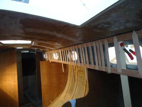
Next I finished up all the overhead with the exception of under the foredeck. I was able to complete about half of the cleats under the side decks. All of these are of course only temporarily installed with self-tapping screws. Once I have them all in and I am satisfied with the fit, I'll remove them and apply quick set 5200. Then I'll use the screws to put them back in place till the 5200 cures then remove the screws.
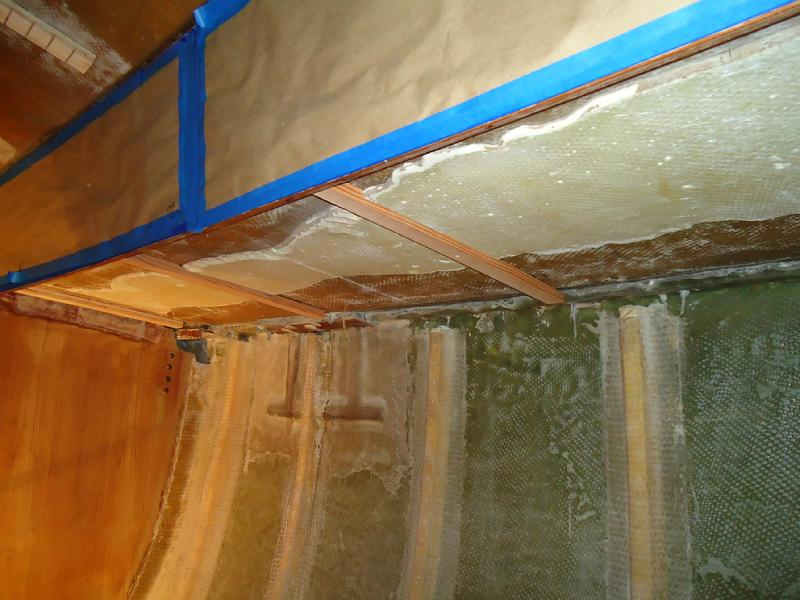
This is more time consuming than I thought it would be. There are so many imperfections in the underside of the deck that it takes all kinds of grinding, beveling ,and shimming of the cleats to get a good fit. Also, in the bottom photo you can see the original mastic adhesive that held the one piece fiberglass overhead liner to the underside of the deck. Last year when I was grinding the inside of the boat I attempted to grind this stuff off and it got the better of me. It was a beast. I don't give up on anything easily but after hours of holding a high speed grinder with a 30 grit flapper disk overhead (I easily went through a half dozen of these supper aggressive disks) I reconsidered the necessity for removing it. I stayed with it long enough to remove the mastic from around the bulkheads where they needed to be tabbed in but that was about it. So, I am paying for it now since I have to to notch the side deck cleats to span the mastic. Each of the side deck cleats, except the ones next to the bulkheads, has to be scribed then trimmed with a jigsaw. Plywood does not scribe that well when cutting the long axis so I have been using Douglas Fir for these. The one good think about the side deck cleats is I don't have to cut kerfs. The mastic is very tough. Last year, before I made my decision to leave it be, I tested its strength by epoxy taping a small piece of wood to it. After it cured I could not break it off and had to grind it down. So, it is pretty strong and there should be no problem using 5200 to secure the cleats to it. Besides, the cleats and the v-groove panels they will support are not structural.
With luck, I'll finish up the cleats tomorrow then I can get organized to install them permanently.
I experimented with several techniques to trim some test cleats to span the old mastic adhesive. I didn't like the way any of them came out. So, I marked a path where each cleat would span the side deck, got a chisel and mallet, and chipped it away. It took about two hours. Then, I suited up with the tyvek paper suit, respirator, and gloves. Armed with the Porter Cable DA right angle, RO sander and 40 grit hooked to the vacuum, I cleaned up the path. Problem solved. I spent the rest of the day cutting, trimming, and installing all the remaining cleats. Tomorrow, I'll check them over and make any corrections necessary. Then I'll apply quick set 5200 to secure them in place.
Lot's of progress the last two days. All the over-head and under side-deck cleats were installed with 5200. All the kerfs were filled with cabosil thickened epoxy. Tomorrow I'll bush on unthickened epoxy to the edge grain of the plywood cleats. Pictures to follow. Vikings-Patriots game and Trick-or-Treating has priority.
The next day I applied two coats of epoxy to the centerline cleats and then pulled down the brown paper that had been protecting the mahogany plywood cabin sides. I was concerned about the tape pulling off some of the wood since it had been on there for nearly three weeks. I very carefully applied a little heat from a heat gun and the tape came right off. In a few places there was some tape residue so I wiped it down with some denatured alcohol.
In the photo to the right you can see the 5200 bead that holds the cleats to the overhead as well as the epoxy filled kerfs. It took a lot of time to get them filled. I have not yet scrubbed the epoxy on the cleats with water to remove the amine blush. Because the cleats are overhead I did not want to drip any water down the unprotected cabin sides. The plan is to get three coats of varnish on the cabin sides and coat the edge grain on the porthole openings with epoxy. Then scrub the cleats down. We are expecting rain for the next three days so no varnish till the end of the week.
After working on the cleats I spent some time determining the footprint for the Refleks heater. Once I make a decision about that I can make the cut in the starboard settee locker bottom that will support the platform for the heater then I can glass in the locker bottom. However, I am not sure what the next task will be. I will sort it out in the morning. I may start milling the African Mahogany I'll use for the vertical staving or I may glass in the locker bottoms. Then again, I can't go much further before I epoxy in the copper foil tape for the HF radio. It's just a question of the proper sequencing for the next couple of steps.
It feels good to be moving along. I am looking forward to roughing in some of the furniture. Though I have made a lot of progress, I still can't see any light at the end of the tunnel. No matter, I know its out there. Just got to keep eating the elephant a bite at a time.
Personal business took up much of the day. When completed, I checked the weather report for the next few days to see when I could start varnishing and learned that we will have lows in the high 30s starting tomorrow night. I have been thinking about how I will keep the inside of the boat warm this winter. This will be important if I am to be able to epoxy, glue, and varnish once the temperatures drop. So, I spent the afternoon developing a simple system for keeping the heat in the boat.
When I go to Lowe's to pick something up I always walk down the aisle that has insulation on it. I am always interested in what they have that I might be able to use for hull and icebox insulation. For the last year or so I have noticed a product called Reflectix. It is essentially a double layer of bubble wrap, 5/16" thick, with reflective foil on both sides. When my son and I sailed on Bill Primeau's boat in Halifax this summer he made a point of showing me how he had used Reflectix to insulate his boat and how happy he was with the performance of this material. Last week, I ran across an article in the back of the Nov Ocean Navigator that described using Reflectix as a hull insulator. So, I went to Lowes this afternoon and picked up the smallest roll of Reflectix they had. I took the plywood "cut-outs" from the plywood cabin sides and stapled some reflectix to it. Then I pressed them into the openings in the cabin sides. They filled the holes nicely. They are just pressed in there. I then made a template from 1/4" ply to fit the dorade and mast openings and did the same for these holes. It looks like it may do the trick. Next, I cut some 2'x2' squares from some scrap plywood and attached thin foam weather strip to the align with the flange on the hatch opening in the forward and main cabin. Tomorrow I'll make something similar for the companionway hatch. With all these openings plugged I believe I'll be able to keep the inside of the boat warm enough with a couple of electric space heaters this winter so that I can epoxy, glue, and varnish. What appeals to me about this system is it mostly used what I had on hand, it was easy to throw together, and I can quickly remove them as the SRF heats up from the solar heat during the day then plug them up as the temps fall in the afternoon.
I'll run some tests over the next few days to see how warm I can keep the boat when the temperatures drop into the 30s. Since the hull is not insulated, I'll need to also see if I get a lot of condensation and, if so, where it forms to better understand how it might also cause a problem for the curing of glue and epoxy.
Reflectix Insulation to keep the heat in the boat.
The AP foam will be applied right over the old mastic that held the one pice head liner in place. It was beastly to remove so I left it in place except where cleats need to be installed.
I spent most of today installing the cleats under the foredeck necessary to complete the insulation project. I installed these cleats in the same manner as the others. I ripped some left over BS 1088 3/4" ply into strips about 1 1/2" wide and cut them length wise to fit as required. I cut kerfs in to the strips so they would bend easily to match the camber of the underside of the deck (those that needed to bend). I made the cuts on the table saw with the miter cut push bar. After test fitting I installed them with 3M 5200 and small self tapping screws to hold them in place till the 5200 cures. Tomorrow, I will fill all the kerfs with thickened epoxy and also apply several coats of unthickend epoxy to the cleats to protect them from moisture.
Installing the Overhead Insulation
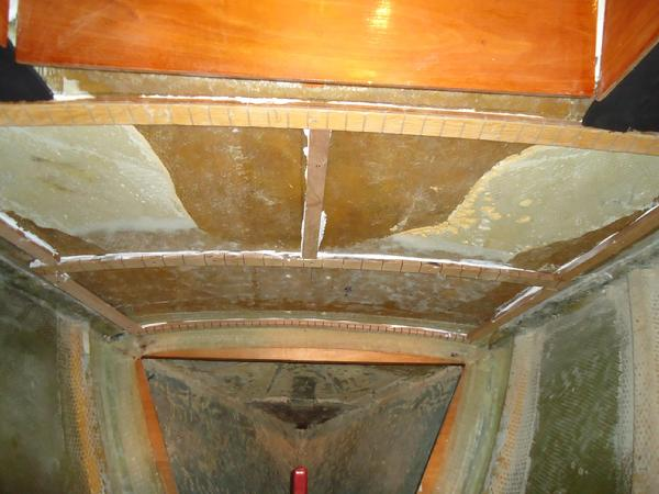
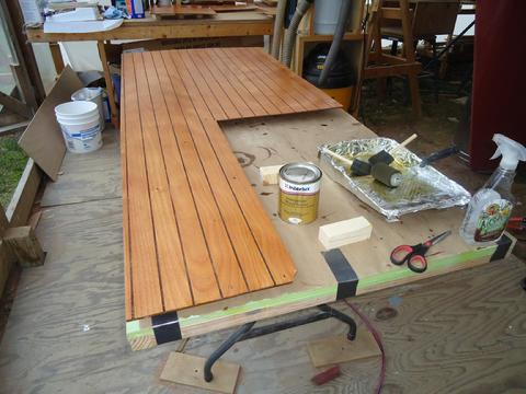
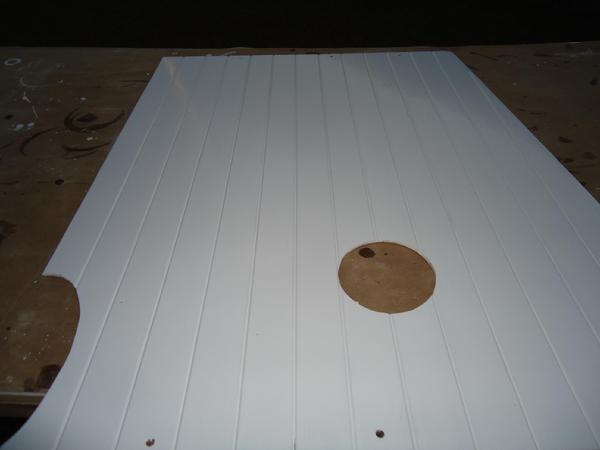
11 Oct 11I got a late start today. I ordered the Kiwi-Grip non-skid and some other supplies for upcoming projects. Ordering supplies and planning each project takes a lot of time. Then, my daughter wanted to make home made bread so we did. Finally, made it out to the boat. I spent about two hours or so installing the first of the 1/2" Armaflex AP foam which I am using as overhead insulation. This was plesant work. The AP foam comes in either plain or self adhesive versions. I chose the slightly more expensive self adhesive foam. The adhesive side is protected with a thin film of white plastic sheeting. I measured the space that I wanted to apply the foam to and recorded the measurements via a diagram I drew out on a piece of paper. Then, I laid the foam face down on the assembly table under the stern of the Far Reach. I transferred the measurements to the white plastic side of the foam with a pencil. Next, with the foam still face down I cut along the line with a sharp filet knife. It worked very well. Then I took the piece up to the boat and test fit it. I wiped the overhead down with denatured alcohol and paper towel. Finally, I pulled the plastic part way off, stuck the foam on and peeled the rest of the plastic off as I pressed the foam in place. The foam followed the conturs of the overhead without any problems. You can see in one photo, near the centerline, the undulations in the overhead and how the foam adhered to the shape of the surface it was stuck to.
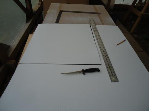
This is the back side of the foam. The adhesive is covered by thin white plastic sheeting that you peel off to get to the adhesive. All you need to cut the foam is a sharp filet knife.

This is the self adhesive sticky back membrane. It is very sticky and well worth the little extra expense. Otherwise you would have to buy contact cement and it would be a mess not to mention take a lot more time to apply.
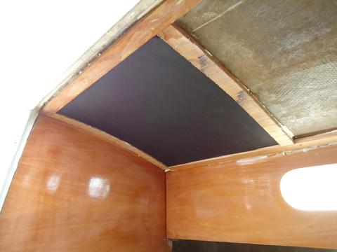
The first piece of foam in position.
It took about two hours of easy work to apply the foam to the saloon overhead. It will get more difficult as the spaces get smaller and harder to fit.
4 Nov 11: One Step Forward and Two Steps BackI spent the last couple of days installing the overhead "v-groove" panels in the main cabin. I bought five sheets of 1/4" Okume BS 1088 ply to make sure I would have enough for the job with a little left over to start the underside of the decks. Even though the back side of the ply will be coated with a couple of coats of epoxy I wanted good quality ply in case there are any condensation issues in the overhead. After bringing the ply home, I made patterns with strips of 3/32" door skin ply and a hot glue gun. I laid the patterns over the 1088, traced it out, cut the panel, and then test fit it holding it in place with a couple of braces. Next I used a guide bar, a jig I made, and my router with a V groove bit to cut the grooves. I made the v-grooves 2" apart. I installed two panels and was over half way complete with the main cabin and was working on the third panel when the veneer separated from the core. To say I was disappointed is an understatement. BS 1088 is the gold standard for marine plywood. I called Atlantic Veneer where I buy all my plywood and some domestic hardwood. They agreed to take it all back and replace it with 1088 from another manufacturer. So, as much dislike covering the same ground twice I will take down the two panels I already installed and start over. It will cost me about two days work but I don't have any confidence in this plywood.
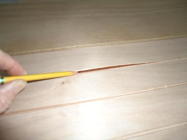
BS 1088 veneer separation.
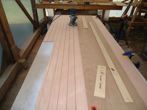
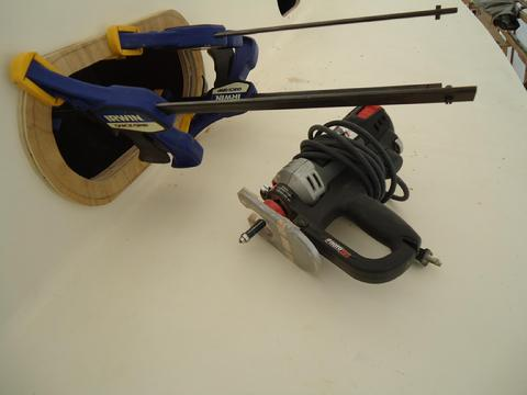
These are the tools I used. Plywood as a guide bar and clamps to hold it in place. A straight edge that sets the distance between the V-grooves. Two spacer blocks that match the distance between the edge of the router and the center of the V-bit. A Bosch router with a V-bit.
Two panels in position.

The third panel being test fit. I'll install the insulation above this panel once I cut the hole in the overhead for the flue.
Three panels installed. Beams will cover the screw holes.
5 Nov 11This morning I drove to Atlantic Veneer and swapped out the defective 1088 ply for new ply from a different manufacturer. As soon as I returned home I got right to work. First, I removed the panels I installed yesterday since they were from the same defective lot of plywood. I used them for templates and traced them onto the new plywood. Then, I cut the panels out, routered the V-grooves, and installed them. At that point I was caught up to where I was when the veneer peeled off the defective plywood. So, I laid the doorskin template out on the ply, traced it, cut out the pattern, and routered the V-grooves on it. I temporarily installed it with braces holding it in place. I traced the hatch opening onto the backside of the ply from the deck of the boat. I removed the panel and cut out the opening and then installed it with screws.
The trick to this kind of projects is to establish a single datum point, in this case it is the centerline of the boat on the overhead. I build each template from the centerline and work outboard. I also build each template aligned with the previously installed panel so I know that they will line up and fit together.
To make the seam invisible down the centerline of the boat, I cut a half V-groove on each panel, port and starboard sides. When I installed them they formed a V-groove on the centerline which blends in perfectly with the other V-grooves. Eventually, we will laminate and install 'thwarship beams about every 26". They will hide the screw and joint lines.
6 Nov 11I completed installing the overhead panels in the main cabin and the head compartment. There is a little misalignment on the v-grooves on the starboard side between the aft most panel and the one just forward of it. I did not pre-mark the groves and they grew a little further out of alignment from the centerline towards the outboard edge. There will be a beam there and it should break the sight-line so no worries. So far I am pleased with the progress.
Happy Birthday Dad--you would be 89 years old today.
Happy Birthday Dad--you would be 89 years old today.
7 Nov 11Progress was slowed today. I spent some time figuring out how I was going to install the panels under the deck. After considerable thought I decided not to cut the v-grooves on the panels under the deck. The fact that not cutting the grooves would simplify the installation had no bearing on the decision. In the end it came down to the fact that there is no straight centerline to serve as a common reference point for the grooves under the side decks. Both sides curve--inboard and outboard edges. This would make lining up the v-grooves problematic. The overhead of the forward cabin is almost complete.
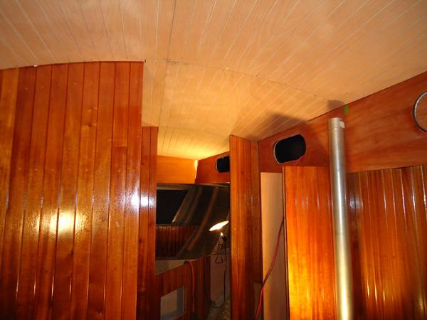
I like the color of the varnished mahogany under incandesent lighting.
8 Nov 11Today I completed the fitting of the forward cabin overhead panels. I installed the last v-groove panel on the portside of the forward hatch. Then I made the cut out for the hatch and set right to work finishing off the underside of the deck in the forward compartment. The two seams in the panels over the head of the double berth will eventually be covered with trim. I am pleased with how the installation is going. I continue to make patterns in doorskin strips and the hot glue gun. Not much too it but it is kind of tedious and time consuming. I think I'll need to pick up another three sheets of plywood to finish off the boat.
10 Nov 11I spent most of yesterday building the remaining templates for the overhead panels. Today I built the templates for the underside of the deck over the quarter berth (these will all be painted white with a varnished beam across each end and two across the middle). Starting yesterday I left all the templates stapled in place. As soon as I built the last one I pulled the templates down from above the port and starboard quaterberth. I traced the templates on 1/4" 1088 ply, cut them out, and fit them into position with a minimum number of #8 1" self tapping ss screws. I braced the panels into position and then predrilled the holes with a combination drill bit/countersink installed in one cordless drill, then drove the screws in with another cordless drill. I always drill each hole then install a screw before I drill another hole to make sure the holes line up properly. It goes pretty fast. The full size 76"x24" panels went in pretty easy as a single piece. But, after thinking about it some this afternoon I think I may take them down tomorrow and cut them into two pieces so they will be easier to remove once all the trim is installed. I have to be careful not to install anything I can't remove without disassembling half the boat. I finished up the day cutting out and installing the panel over the galley area.
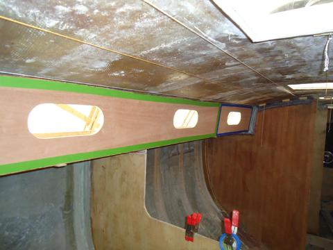
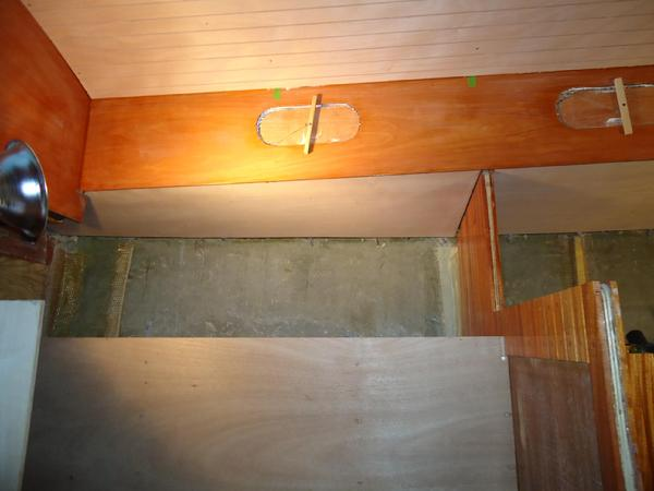
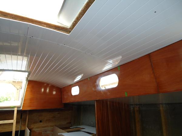
At the top of the photo to the right are the v-groove cabin top panels. In the center of the photo, under the side-deck are the panels above the galley area and portside pilot berth. The green tape marks the location of beams so I drilled in the correct place when I first installed the panels.
At the top of the photo to the right are the v-groove cabin top panels. In the center of the photo, under the side-deck are the panels above the galley area and portside pilot berth. The green tape marks the location of beams so I drilled in the correct place when I first installed the panels.
Today, I completed the cutting and temporary installation of the remaining overhead panels. I used up nearly all the 1/4" ply. For the record, it took seven 4' x 8' sheets of plywood (about $350) to install the overhead for the cabin top and under the side decks. I estimate there is about 200 sq ft of overhead in the living spaces of the Cape Dory 36. The next task is to remove the panels and apply a couple of coats of epoxy to the back side of the panels. After it has cured, I'll start the priming and painting of the inside faces of the panels.
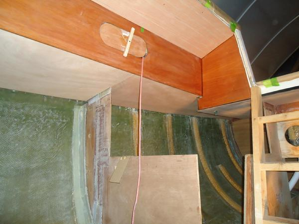
Looking aft towards the navigation and quarterberth area on the starboard side.
16 Nov 11This is a running entry for this project.
For the last four days I have continued working on the overhead panels. I removed them from the boat and set up some plank supports to hold them in the shed while we perform the sanding, sealing, priming, and painting. It was not till I laid the panels out on our back deck that I really got a feel for just how many panels we would be dealing with. I started off by sanding the backs of the panels with 80 grit paper and applying two coats of West Epoxy. After the epoxy cured I flipped the panels over and sanded the interior side with 120 grit paper. Then I began sealing the wood with Interlux Inter Prime Wood Sealer. The tech department at Interlux recommended I seal the ply wood before we prime and paint with Brightside LPU. They said the sealing would prevent the primer from being sucked up into the exposed end grain where I routered the V-grooves. After the first coat dried overnight, we lightly sanded the panels again and applied the second coat of sealer. We have some rainy weather coming so I don't know if I will be able to start applying the Prime-Kote primer tomorrow.
19 Nov: For the last two days we had cold weather so we did not prime the panels until this morning. Today the temps got up to about 65 degrees with night time low forecasted for about 55 degrees. We are supposed to have about five days of nice weather. We used Interlux Pre-Kote. No major issues. We rolled and tipped. It took about three hours. If they are dry enough to sand tomorrow we will apply another coat.
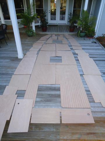
There are more overhead panels in the boat than I thought.
One of the panels after the second coat of Interlux Interprime wood Sealer.
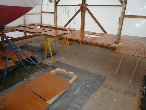
All the panels laid out for drying.
The first coat of primer, rolled and tipped.
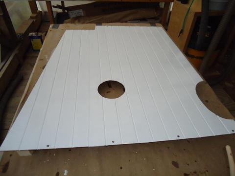
20 Nov 11After looking the primered panels over this morning we decided to go ahead and roll and tip Brightside. The paint handled well, laid down flat, and was very glossy. Tomorrow we will sand and roll on another coat.
The V-groove panels were more difficult. Yesterday, when we applied the primer to the V-grooves with a brush and then rolled and tipped the panels it went on thicker than we anticipated. When we went to sand them this morning the primer had not cured enough to sand without tearing. So we set the V-groove panels aside and concentrated on the flat panels where the primer went on thinner. Later we went back and sanded carefully and primed one of the V-groove panels and applied a coat of Brightside. It came out pretty good. However, if you look closely you can see some of the tear out in the V-grooves. We left the rest of the panels to further cure. They will need more primer to address the tear out unless I come up with a different plan.
The V-groove panels were more difficult. Yesterday, when we applied the primer to the V-grooves with a brush and then rolled and tipped the panels it went on thicker than we anticipated. When we went to sand them this morning the primer had not cured enough to sand without tearing. So we set the V-groove panels aside and concentrated on the flat panels where the primer went on thinner. Later we went back and sanded carefully and primed one of the V-groove panels and applied a coat of Brightside. It came out pretty good. However, if you look closely you can see some of the tear out in the V-grooves. We left the rest of the panels to further cure. They will need more primer to address the tear out unless I come up with a different plan.
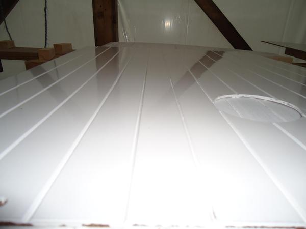
You can see a little bit of tear out in the endgrain of the ply in the v-grooves.
One coat of primer and one coat of Brightside.xt
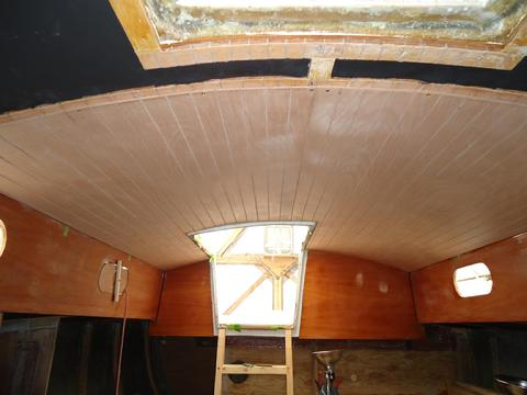
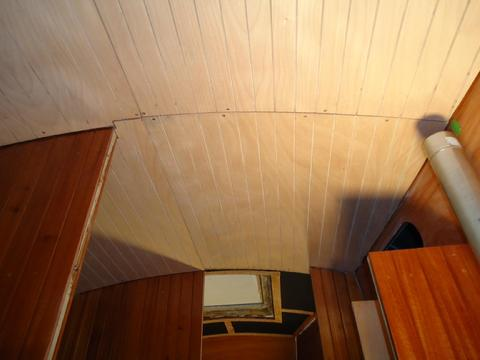
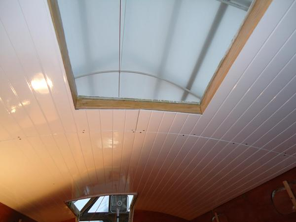
3 Dec 11This morning I installed all but two of the overhead v-groove panels. I am very pleased with how they came out. I could not install two panels as I failed to cover the wood cleats that surround the opening for the dorades with epoxy. So, I installed all the other panels and coated the wood with a couple of coats of epoxy. Tomorrow, I'll install the remaining two panels.
The panels fit together down the centerline very nicely except for about 24" forward of the saloon deck hatch. Not sure why. It is a very small gap. I can't really do anything about it so I will get covered with mahogany trim and will blend in just fine with the deck beams and hatch trim.
The panels fit together down the centerline very nicely except for about 24" forward of the saloon deck hatch. Not sure why. It is a very small gap. I can't really do anything about it so I will get covered with mahogany trim and will blend in just fine with the deck beams and hatch trim.
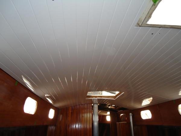
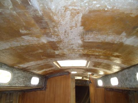
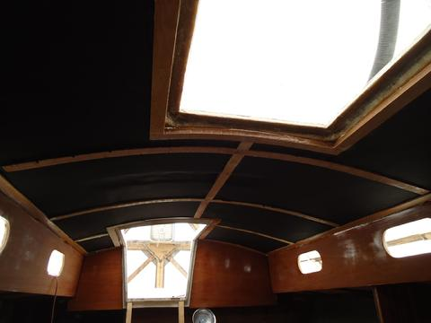
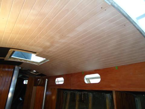
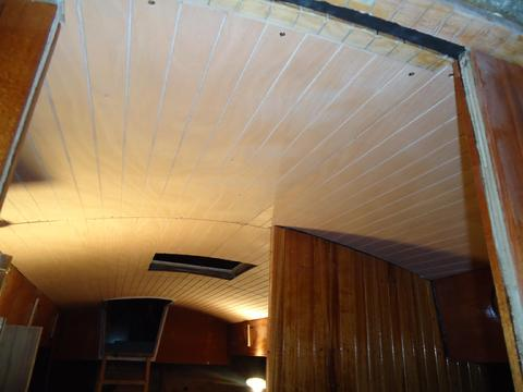
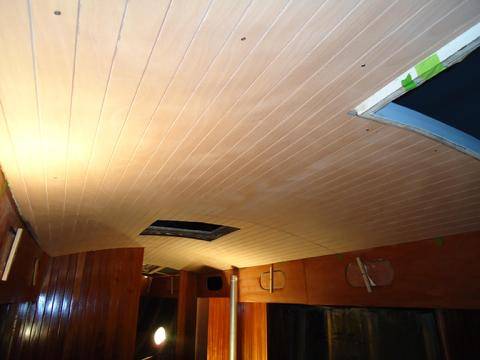
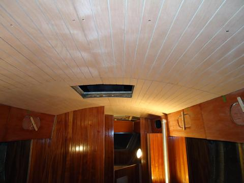
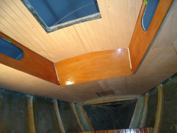
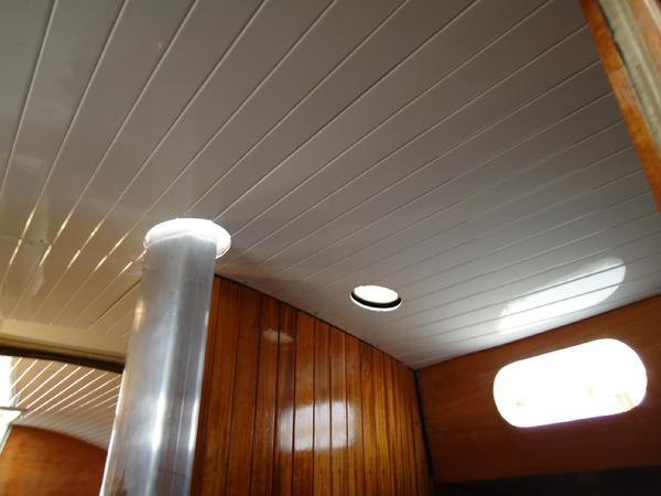
4 Dec 11To the right are a couple more pictures of the overhead v-groove panels after I installed the last two in the head compartment. I am very pleased with how the panels turned out. If you know what you are looking for you can see a little end grain tear out here and there in the v-grooves. But if you weren't looking for it I don't think you would see it. The white overhead really brightens up the interior. Plus, I was sick of looking at the unfinished fiberglass for the last 2 1/2 years.
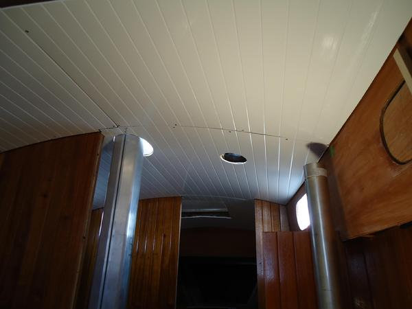
Looking forward from the saloon to the head compartment. To the right is the flue for the Refleks heater. It will eventually pass throught he overhead.
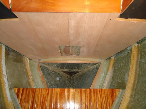
While also working on the windvane I built and installed the frames for the deck hatches. These frame will not be visible. They span the gap between the open edge of the overhead panels and the fiberglass ovehead around the hatches . They also provide a surface for the vertical and horizontal finish trim to screw into. Though a precise fit was not required it still required tedious time consuming work.
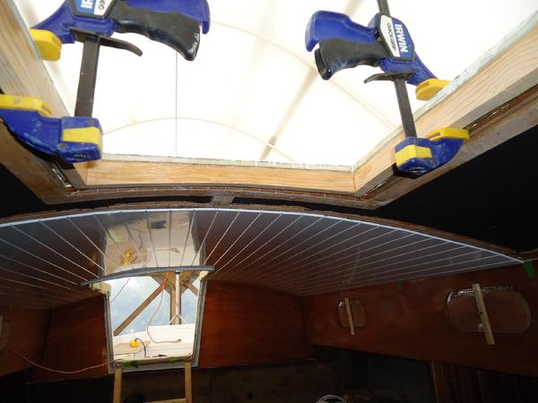
I built mock ups with cheap 2x4 white pine to serve as a template for the final product. Once I was satisfied with the mock-ups, I milled some 2x6 Douglas Fir to 1" thick. Then I ripped it to 2 1/2" wide on the table saw and cut them to length on the chop saw. I scribed the curves from the mock-ups and used my jig saw to cut the curve which also had to be cut at an angle to match the camber of the deck. I made sure they were square and glued them up, clamped them, and left them on my work table over night. The next day, I dropped the overhead panels around the hatches and installed the frames with thickened epoxy. I clamped them in place and let them cure overnight. Next day, I removed the clamps and reinstalled the panels.
For the next phase, trimming out the overhead, click here and scroll to the overhead trim section.